Smart Switches
Smart Switches are the manual control switches used for the HortiMaX-Go!. These switches are equipped with an electrical circuit, a processor and software. The Smart Switches perform specific control actions for the equipment connected to them. The switches are advanced control devices that can process a wide range of information, such as status and position detection, and run and operating times. Your installation engineer can also connect various contacts to the switches, such as end contacts, emergency stop contacts and thermal cut-out contacts (also called 'thermal protector contacts'). The Smart Switches can use the collected status information to control the equipment in your greenhouse, and can also relay that information to the central HortiMaX-Go! controller. This greatly enhances the reliability of the system, and enables alarms to be triggered instantly should something go wrong with your equipment.
The main components of the Smart Switches are:
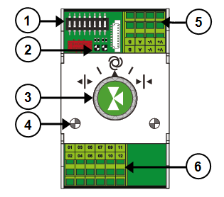
- DIP switch for setting the Smart Switch address
 Read more
 - LED indicators for bus communication Read more
- Manual control knob (optional) Read more
- LED indicators for operation Read more
- Power supply and bus connections Read more
- Connection for peripheral equipment Read more
DIP switch
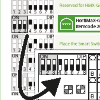
Up to 32 Smart Switches can be connected to the HortiMaX-Go!. To install Smart Switches, you first need to assign addresses to the Smart Switches. Each Smart Switch requires a unique address. This address is set using the DIP switch. By moving the small toggle switches (or 'DIPs') up or down, you can set a binary number that will be used as the Smart Switch address. Using the address list provided, you can set a unique address or DIP switch position for each Smart Switch.
Every system includes an alarm/weather Smart Switch with address 0, or all DIPs in the down position. The other switches in the system need to be assigned to a specific zone in the greenhouse. Every zone is equipped with an MTV-Go! sensor unit. DIP switches 1, 2 and 3 determine which zone the Smart Switch is assigned to. Multiple Smart Switches may be assigned to the same zone.
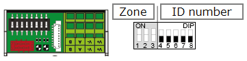
Figure 30: DIP switch
DIP switches 4, 5, 6, 7 and 8 determine the unique address or ID number of the Smart Switch (called 'DIP switch position’ in the software). This ID number may only occur once in each HortiMaX-Go! system.
Setting the DIP switch address
-
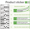
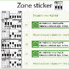
Place the product sticker, included with the Smart Switch, in an empty spot on the wiring list.
-
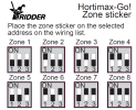
Determine up to which zone you want to assign the Smart Switch (1 - 8). On the wiring list, place the relevant 'zone sticker' on the line of the Smart Switch next to the ID number.
-
Set the DIP switch on the Smart Switch to the DIP switch position shown on the wiring list.
If two Smart Switches are assigned the same address, one or both Smart Switches may not be detected during scanning. Even if one of the Smart Switches is detected, the system will be unable to use it because data from the other Smart Switch will also be coming in. The scanning screen will display 'address conflict'.
LED indicators for bus communication
The switches are connected to each other using a 'fieldbus system'. The fieldbus system enables digital communication between the switches and the controller via a network cable.
When the LED is lit green, it indicates that communication is occurring. When the LED is lit red continuously, it indicates that no communication is possible. This may have various causes:
- Controller failure
- Broken cable
- Wrong cable used
- Power failure at one of the connected switches
- Failure of one or more switches
- Disruption by an external factor such as a frequency controller or high-voltage cable
- Incorrect ID address (DIP switch position)
- Incorrect or duplicate terminal resistance installed.
When the LED is lit red, check whether a connection can be made.
Communication problems due to incorrect installation may sometimes only arise after some time or after a system expansion. To avoid such problems, make sure to observe the installation instructions.
Manual control knob
The manual control knob on the Smart Switches can either be used to disable automatic control and operate the connected equipment manually, or it can be used to switch the equipment off. If you switch to manual control, the controller will continue to keep track of the status or position of your equipment. This unique feature means that the controller is able to monitor the current situation and the operating times of your equipment with much greater accuracy.
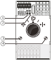
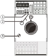
Depending on the Smart Switch, the manual control knob has:
- Three positions (on/off/automatic), or
- Five positions (on/off/automatic/open/closed).
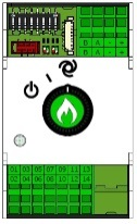
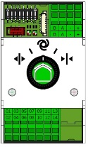
Figure 31: Smart Switches with three and five positions
If you use the switch to operate the equipment manually, then all automatic controls will be disabled. The tile headers of the relevant controls will turn orange and will display the following icon:  .
.
If you turn the control knob back from manual to automatic mode, then the controller will immediately adjust the equipment to the preprogrammed position(s). This is unlike conventional switches where the controls first need to be reset or synchronized.
If the controller and/or bus communication are non-operational, then the Smart Switches will be unable to control the equipment automatically. However, using the control knob, you will still be able to adjust the Smart Switches manually, so you can turn equipment on / off, or, open / close it. In this situation, the equipment positions and operating times shown by the controller may differ from their actual values.
LED indicators for operation
The Smart Switches are equipped with two types of LEDs on the bottom circuit board and the switch covers. Listed below are the meanings of the different LED indications:
| 1: Green continuous | Communication has been established with the HortiMaX-Go!. | 1: Red continuous | No communication has been established with the HortiMaX-Go!. Check whether a connection can be made. |
| 1: Green flashing | Smart Switch control is active; the Smart Switch is controlling the device in question. | 1: Red flashing | Smart Switch control is active, but the connected device has triggered an alarm. Check the device and remedy the fault. |
| 2: Green | The Smart Switch is receiving data via the bus. | 2: Red | The Smart Switch is sending data via the bus. |
| 3: Green continuous | The open output is active. (For example, a vent is being opened.) | 4: Red continuous | The close output is active. (For example, a vent is being closed.) |
| 3: Green flashing | The open end position has been reached. (For example: a vent is 100% open.) | 4: Red flashing | The close end position has been reached. (For example, the vent is closed.) |
| 5: Green continuous | The output is active. (For example: the pump is switched on.) | 3,4: Green and Red flashing | Emergency contact (normally closed contact) is active. (Example: Vent emergency stop.) |
Location and connection requirements
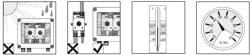
Smart Switches are not moisture-resistant and have an IP rating of 20. Install the Smart Switch in a sealed cabinet that will protect the Smart Switch from moisture (IP65). Avoid direct sunlight on the Smart Switch cabinets. Ensure that the temperature remains between -10°C and 50°C. Ensure that the humidity level remains between 5% and 95% (no condensation).
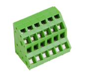
The connection terminals are spring terminals.
Wiring requirements:
- Use ferrules if stranded wires are used.
- Use wires with a minimum diameter of 0.14 mm² and a maximum diameter of 2.5 mm². AWG 28-14.
- The desired length of a stripped wire is 6.0 mm.
- Use the screwdriver provided (VDE, flat, 4.0 mm) to unlock a spring terminal.
Connecting equipment and contacts
Terminals 1-14 on the underside of the Smart Switch are the connections for inputs and outputs. The control signals and various contacts of the existing equipment are connected to these input and output connections.
Always observe the connection instructions that are provided with the equipment. The Smart Switch outputs can send a plus or minus DC24V control signal, depending on whether the connection to the common is plus or minus.
Before connecting the limit contacts, remove the wire bridges. This functionality needs to be set up on the controller.
Most equipment is protected by a PKZ thermal cut-out (also called a 'thermal protector'). Most PKZ cut-outs are equipped with an auxiliary contact that is connected to the controller I/Os. Remove the wire bridge and connect the output of the PKZ cut-out. The controller will generate an alarm alert if a thermal cut-out is tripped. You can also connect the PKZ alarm outputs of multiple devices in series (as a 'daisy chain'), in which case the alarm will also apply for the group of connected devices. In the event of an alarm, climate and irrigation control will remain active. However, the power supply to the equipment causing the alarm will be interrupted.
Use auxiliary relays if multiple devices need to be connected to one output or an AC control current is required. The maximum power level that can be controlled is 5 Watts.